



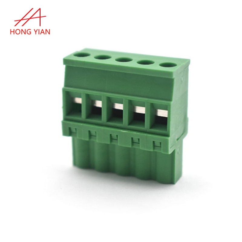

Where 5.0 mm sits in the pitch ladder
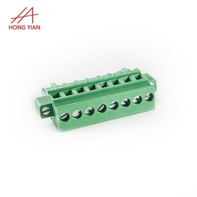
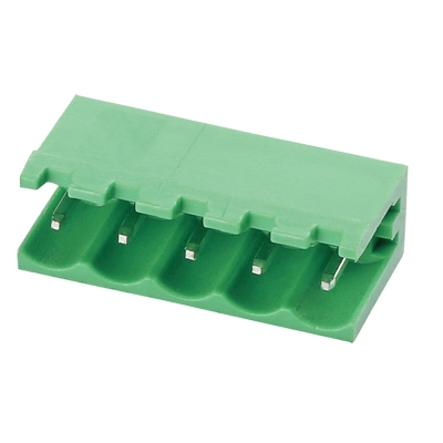
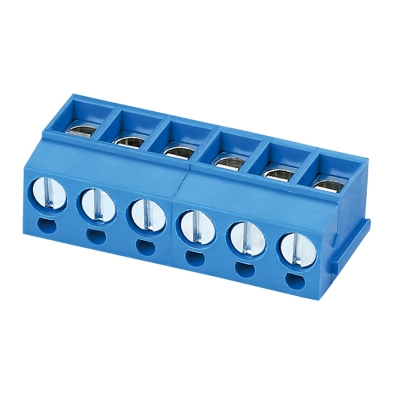
Terminal blocks climb a pitch ladder and each rung buys room for the screw, the wire and the creepage path between neighbours. At 5.0 mm this block lands one step below the common 5.08 mm spacing, close enough that most board layouts accept it without a redesign. The screw terminal suits a wire that will be landed once and left. Move down to 3.81 mm and current falls with the spacing; move up to 7.62 mm and the barrier grows. Pick the rung for the wire gauge and the clearance you actually have.
The screw, the clamp and four and a half watts
The rating is 15.0 A typical at 300 V AC typical, with contact resistance at 20 mΩ max. That pair matters more than it looks: at full current a single contact dissipates about 4.5 W, so a loose screw is a heating fault, not a nuisance. Torque the screw to the figure in the terminal maker's data sheet, then recheck after the first thermal cycle because the plastic creeps. Insulation resistance is 100 MΩ min and the dielectric proof runs at 2500 V AC typical across the closed block.
Building the block to your pole count
Send the pole count and the wire entry side you want and we will quote the block from the drawing rather than a catalogue row. Standard builds leave in eight working days, which keeps a pilot panel on schedule. For a layout still moving, our engineers return a DFM note in 2 to 4 hours before any tooling is committed. Either way the pin map stays with the order so the second build reads like the first.
 008613534059456
 whatsapp:joy
 overseas@hongyian.cn
